I ordered in a 5″ TFT LCD with resistive touch screen, along with Adafuit’s RA8875 Driver Board for 40-pin TFT Touch Displays. These are just some notes and comments of my experience in getting it all working.
Making the connections.
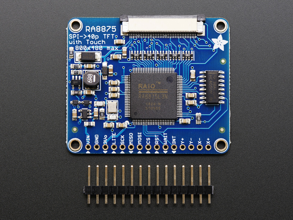
First thing to make clear is that the driver board from Adafruit DOES have level shifting on it, and can be connected to both 3.3V and 5V systems. Let me also be clear that although it will work with a mixture of voltage signals (as I found out), you should PICK ONE.
Connections:
- Vin: +3.3V (** OR +5V)
- GND: GND
- 3Vo: NC (** 3.3V out from the on-board regulator)
- Lite: NC (** Can be used to turn backlight off)
- SCK: SPI SCK
- MISO: SPI MISO (** MISO is NOT tri-stated and cannot be used with other SPI devices without 74HC125 or similar)
- MOSI: SPI MOSI
- CS: SPI CS
- RST: Active Low – connect to any available MCU pin
- WAIT: Active Low – connect to any available MCU pin
- INT: Active Low – connect to any available MCU pin (** or INT pin if you want to use interrupts)
- Y+: NC (** Optional, external touch screen controller)
- Y-:NC (** Optional, external touch screen controller)
- X+:NC (** Optional, external touch screen controller)
- Y-:NC (** Optional, external touch screen controller)
Here are the basic connections made for my setup, which includes the RA8875 driver board, a PIC18F46J11 (3.3V) (44-pin TQFP breakout from Adafruit) and an SD/MMC card breakout from Sparkfun. Top right is voltage regulation. 9VDC in, 3.3V out on the left and 5V out on the right. One thing to note here is I had to use a 10K pullup on the MISO of the SD card to get it to work.

Code used for these tests was ported from a combination of places, including Adafruit, AtomSoftTech, the RA8875 datasheet and AppNote from RAIO, Sumotoy and a few others I’ve probably missed right now, but will add as I remember / find links. Most of it is for Arduino, so I ported it to Microchip, which I will make available via GitHub as soon as I break it down and clean it up. Right now I have every test I’ve done all crammed into one file, some of it not working without modifications as a lot of it is RAM intensive.
My first test was a port of the buildtest sketch, included with the Adafuit_RA8875 project. There were no real problems getting this to work. The only real note that comes to mind is, if you get a screen that looks like the one below, don’t automatically assume it’s your SPI timing, etc.. The problem in my case was the use of 8 bit registers for the display size (X / Y), so the initialization was failing – I just didn’t realize it.

The Buildtest Sketch
Once I fixed the registers (made them 16 bit), everything worked as expected. There are a few things missing from this image, such as the curve and line tests. I simply didn’t have them in the code at the time of taking this picture. It works, pretty much, identical to the Adafruit buildtest sketch (except I brought the circle to the front as it was being drawn first and overdrawn by the rectangle).

The TS_calibration Sketch.
The next test was the Adafruit ts_calibration sketch. Again, no real problems here. I have not yet saved the calibration matrix to eeprom so the process does not have to be repeated each time the system is power cycled. This is simply for testing the process. Four calibration points are placed on the screen, one at a time. Touch them, as they appear, to calibrate. It’s that simple.

OK, so when I had ordered these items from Adafruit, I tried to do as much research as I could on anything pertaining to the driver board, TFT and touch screen before they got here. That’s when I ran across the AtomSoftTech website, owned and operated by Jason Lopez and, in particular, his RemoteSeven project. Jason has created his own IR remote using a 7″ TFT LCD with capacitive touch from BuyDisplay.com. What I found interesting was how Jason created his GUI, so I made a few comments on his blog and asked him about it. It turns out Jason created his own format (with the file extension .asi) for storing images. I’m getting a little ahead of myself – more on that later.
So, I ported over some of Jason’s code and was able to reproduce the effects of his GUI. Looks good!

So, here’s what I learned from this test. Drawing images of this nature, via SPI, are painstakingly slow. With this PIC running at 32MHz (8MHz with PLL), the main.asi (768kB) image takes about 12 seconds to fully load. I don’t know why, but I didn’t expect that. My initial tests, with the PIC running at 8MHz, produced fall asleep wait times. It reminded me of the 1200 baud BBS days. I’ll have to grab video of it to demonstrate.
If you take a look at some of Jason’s videos, he shows brief use of button use, including image rollover (in the orientation test I noted the volume button rollover). It seemed to produce a nice effect. I actually haven’t gotten that far as to playing around with button presses and rollover images, so I can’t even comment yet on how it’s done or what processor speed Jason is running on the PIC32 he’s using to produce these effects.
Native, Geometric Shapes.
So far, my initial thoughts are that it’s pretty cool for a DIY project, but I really wouldn’t want a 12 second load time in a commercial product. So, what can be done about it? Well, my thoughts are you would need to look at the parallel interface, rather than SPI, but let’s look at drawing our own GUI with the native, hardware accelerated, tools given to us by the RA8875 driver first. Remember the buildtest sketch that was done first? This uses all the native, geometric drawing tools, which use the RA8875 hardware to instantly (seemingly) draw these shapes. Among the shapes are the circle, triangle, rectangle, ellipse, curve, line and circle square. Circle square? That’s what RAIO call it. In English, it’s generally referred to as a rounded rectangle. For whatever reason, most code that I looked at did not include the rounded rectangle, but it was easy to implement from the datasheet. This is what I’ll use to draw my own “soft” buttons. Below is an example.

I think it looks pretty good for a first attempt. The buttons were all drawn using rounded rectangles – three to be exact. One for a border (white), one as a fill (blue) and one as a highlight (light blue). The top box is another rounded rectangle, which will be used as a message area.
You can also see my final test, the drawing of a bitmap image (.bmp), which is another Adafruit sketch included in the Adafruit_RA8875 project.
Image Formats.
This brings me back to image formats. Take a look at the specifications for the BMP file format, found on Wikipedia. You’ll see that in order to read a bitmap (.bmp) file, there are a number of bytes (WORDS / DWORDS) at the beginning of the file that tells us everything we need to know about the image, including size on disk, height, width, color depth and various other bits of useful information. What is worth noting is that this information is stored little-endian. Why this is note-worthy is that “byte-flipping” is needed to rearrange the order of the read register. This is done on every read and uses up quite a bit of processing on an embedded device. By comparison, the included “parrot.bmp” image, which is 61kB, takes approximately 6 seconds to load (half the time it takes Jason’s main.asi (768kB) image to load).
The first thing done is to check the first WORD, which MUST equal 0x4D42 in hex, or BM in ASCII. This tells us we’re dealing with a bitmap file. Then we cycle through the bytes (follow along in the DIB Header Information image) and read the rest of the bytes in the header, saving what we need and discarding what we don’t. Once we’ve done that, we cycle through the image data, one scanline at at time, byte-flipping each read, converting that data to RGB565 color format (from the 24 bit color depth of the bitmap) and writing it to the display.
What Jason has done is he has removed everything from the header that is just not needed for our purposes. This reduced the header information from 40 bytes in the DIB for a bitmap, to 20 bytes for his .asi files. The next thing he did was to convert the 24bit color depth to RGB565 (16bpp) and store it big-endian, so no byte-flipping is necessary. What you read is what you write.
To be fair, I will also mention that although Jason’s 768kB .asi image loads in approximately 12 seconds, the function has been afforded 2MBs of RAM, while the 61kB parrot.bmp loads in approximately 6 seconds, it uses a buffer size of 80 bytes (3 x 20 for the sdbuffer and 1 x 20 bytes for the lcdbuffer).
So, that’s it for today. I’ll update this as I have more information. Questions are always welcome. I’ll help when I can.
UPDATE: I finished up this post late last night and forgot to link the images to their larger versions. It has been corrected.


Great article! Keep it up. I am looking forward to reading more. Since i used a 7 inch screen i was unable to use the layer function. With a 5 inch im not sure if possible but perhaps it is and that would save tons of loading on images.
Thanks for your comments, Jason.
That is yet another feature I have not looked at. As you are aware, documentation for the controller is extensive!
Layers are available for any screen size, you just get limited in your resolution and color depth.
I’ll have another look through your code today and peruse the section on layers and see what I come up with.
Kyle
Hello kyle i want also use RA8875 7″ screen but i am confused about which mcu is proper to this project ? Is PIC18F46J11 good enough for that ? or can u advice me another mcu ?
Hi Ercan;
It really depends on what you want to do, but if you’re looking to use the display for video, or your application is more graphical in nature, an upgraded MCU, like the PIC32 would be helpful. For my particular needs, the PIC18F did a good job.
Kyle